Home »
Our Products » Geotextile/Geosynthetics Testing Instruments
Geotextile/Geosynthetics Testing Instruments
 |
 |
|
Thickness Gauge |
|
|
MI.GE-1001
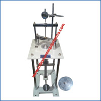
Thickness Gauge for Geotextile / HDPE / Geonet
Meets: - ASTM- D 5199, EN - ISO -9863-1, IS-13162-3, ASTM - D 1777
This is used for measuring the thickness of the Geo-textile, Geo-membrane and many more. The thickness of the material can be measured with an accuracy of 0.001 mm (depend on the dial gauge accuracy) for thickness up to 10 mm with Foot pressure of 6.35 mm, 10 mm and 56.4 mm diameter. Dead weight mechanism is provided to apply desired pressure varying from 2, 20 to 200 kPa. Surface plate is grounded and is rust free to enable reproducible results.
Features
- Table top Modal
- Range 0-12.5 mm (Depend on Dial Gauge accuracy)
- Supplied with Mitutoyo Dial Gauge
- Least count up to 0.001 mm
- Dead Weight Type
- Easy to operated
- Foot pressure Change able
- Granite Base.
- All material made with Steel less Steel (304)
- Flatness up to 0.01 mm
- Adjustable height
- Used to measure all material like Geo-textile, Geo-membrane and many more
Specification
 |
| Foot Pressure size |
Applied Force |
| 6.35 mm diameter |
20, 200 KPA |
| 9.5 mm diameter |
23.4 KPA |
| 10 mm diameter |
2, 20, 200 KPA |
| 28.7 mm diameter |
4.14 KPA |
| 56.4 mm diameter |
2, KPA |
|
 |
Note :- While Placing the order please mention your requirement we also have other test criteria.
ME.GE-1001E Thickness Gauge for Geo-textile, Geo-composite and Drain material
Meets: - ASTM- D 5199, EN - ISO -9863-1, IS-13162-3,
This is used for measuring the thickness of the Geo-textile, Geo-membrane and many more. The thickness of the material can be measured with an accuracy of 0.01 mm (depend on the dial gauge accuracy) for thickness up to 10 mm with Foot pressure of 56.4 mm diameter. Dead weight mechanism is provided to apply desired pressure varying from 2, 20 to 200 kPa. Surface plate is grounded and is rust free to enable reproducible results.
Features
- On Floor Modal
- Range 0-12.5 mm (Depend on Dial Gauge accuracy)
- Supplied with Mitutoyo Dial Gauge
- Least count up to 0.01 mm
- Lever Ration Dead Weight Type
- SS Foot pressure Base
- Foot pressure Change able
- Adjustable height
- Used to measure all material like Geo-textile, Geo-membrane and many more
Specification
 |
| Foot Pressure size |
Applied Force |
| 56.4 mm diameter |
20 and 200 KPA |
|
 |
Note :- While Placing the order please mention your requirement we also have other test criteria.
 |
 |
|
Cone Drop Test |
|
|
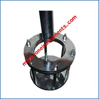
MI.GE-1002
Cone Drop Test Apparatus (Manual)
Meets: - EN-ISO-13433-2006, BS6906: Part 6
Method to determine the resistance of geosynthetics to penetration by steel cone dropped from a fixed height, as a simulation of dropping sharp stones on their surface. Generally applicable to all geosynthetics. However, the test principle may not be applicable to some types of products. The specimen is clamped between two steel rings. A steel cone (45° tip angle, 1000 g) is dropped from a height of 500 mm onto the centre of the specimen. The degree of penetration is measured by insertion of a graduated cone into the hole.
Note: - Electrically cone release facility also available
- On Floor Modal
- Mechanical operated (Electrical release modal also available)
- Sample Size 150 mm (Test able)
- Total Drop height 500 mm ( ± 5 mm Adjustable as per sample thickness)
- Drop cone
- Made of SS material (304)
- Weight 1000 gram
- Angle 45o tip angle
- Having rounded tip
- Measuring cone
- Aluminum materials
- Total weight 600 gram
- Having marking of 1 mm interval for better result
 |
 |
|
Cross Permeability Apparatus |
|
|
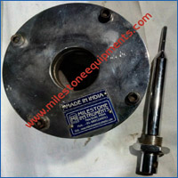
MI.GE-1003
Cross Permeability Test Apparatus
Permeability of a geotextile must be substantially greater than that of the protected soil, so that water can pass freely from the soil through the fabric without build up of hydro static pressure. A high value of the permeability of the geotextile also infers that partial clogging will not reduce the permeability. The constant head test is carried out using a head of 50 mm of water.
Essential Accessories
Overhead Tank
Loading unit, 300-kPa capacity
Cross Permeability Apparatus
 |
 |
|
Permittivity Test |
|
|
ME.GE-1004A
Permittivity Tester
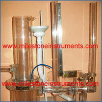
These test methods cover procedures for determining the hydraulic conductivity (water permeability) of geotextiles in terms of permittivity under standard testing conditions, in the uncompressed state. Included are two procedures: the constant head method and the falling head method.
In
Constant Head Test:- A head of 50 mm water is maintained on the geo textile throughout the test. The quantity of flow is measured versus time. The constant head test is used when the flow rate of water through the geotextile is so large that it is difficult to obtain readings of head change versus time in the falling head test.
In
Falling Head Test:- A column of water is allowed to flow through the geo textile and reading of head changes versus time is taken. The flow rate of water through the geo textile shall be slow enough to obtain accurate readings.
- Sample Size: - 50 mm
- Head can be maintain of the sample : up to 40 cm
- Suitable for Both type of test :- Constant Head and Falling
Head.
Meets: - ASTM- D 4491 – 99a, IS-14324, EN ISO 11058
ME.GE-1004I Water Permeability
These test methods cover procedures for determining the hydraulic conductivity (water permeability) of Geotextile under standard testing conditions, in the uncompressed state. The system analyzes the rate of water flow through the specimen as a function by means of a two cylinder- system.
Measurement results are presented on the scale numerically, which is the velocity at a hydraulic height difference of 50 mm.
Meets: - BS EN ISO -11058
Specification:-
TECHNICAL INFORMATION
- Measuring principle: method of vertical flow (without application of load).
- Tested diameter of sample : 50mm.
- Sample diameter :- 72mm
- Thickness of sample :- 0,1-8mm
- Consumption of energy :- 220V AC, 50HZ.
- Comes with 500 ml measuring container.
 |
 |
|
De-Aired Apparatus |
|
|
MI.GE-1004.1 De-Aired Apparatus
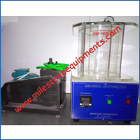
De-Aired tank is designed to remove dissolved gasses from ordinary clean water. The apparatus consists of a closed cylinder with hose attached to vacuum pump provided, which is controlled by PID controller.
Meets :- ASTM D 4491
Capacity : -20 liter
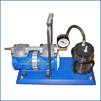
ME.GE-1004.2 Vacuum pump for bubble removing
This is used for removing the air bubble which is on the sample while filling the water on the tank.
 |
 |
|
Dry Sieve Test Apparatus |
|
|
ME.GE-1005.D
Dry Sieve Test Apparatus (Apparent Opening Size (AOS))
ASTM D4751-87, BS-6906-2, IS-14294
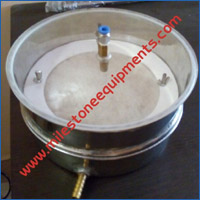
The test involves sieving rounded particle sizes for which 5% or less by weight pass through the geotextile. The Apparent Opening Size (AOS) is defined as ‘Retained On’ size of that fraction expressed as a standard sieve number (size). The test is widely used for relative comparison amongst the geotextiles. Thus AOS is a means of correlating geotextile pore structure to an equivalent screen mesh size. The apparatus consist of a 20 cm dia brass frame with clamp, a receiver and a lid Dry Sieve Test Apparatus.
 |
 |
|
CHARACTERISTICS OF OPENING SIZE (COS) |
|
|
MI.GE-1005.W
CHARACTERISTICS OF OPENING SIZE (COS)
ASTM D4751-87, BS-6906-2, IS-14294
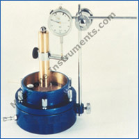
The apparatus comprises a sieving unit, which allows testing of a specimen with an exposed sieving area corresponding having 148 mm diameter with a supported Grid of 1.4 mm diameter and mesh size of (10±1)mm to support the specimen during the test to avoid excessive deformation having the nozzle for discharge of water Fixing on the acrylic sheet cover for viewing the sample during test. The complete set is provided with the pan which has the drain nozzle for collate the water after test.
Essential
Accessories
MI.GE-1005001.01
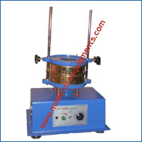
Sieve Shaker Table top type
To make the process of sieving easier and quicker,
electrically operated mechanical table top type sieve shakers are offered
for dry sieving. These Sieve Shakers are popularly used not only in soil
laboratories but also dry sieving the geotextile testing
ME.GE – 1005001.02
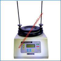
Sieve Shaker (Electromagnetic Type)
ELECTROMAGNETIC SIEVE SHAKER, which have been developed applying the latest technological advances of power control. The sieve shakers micro processor controller is used to set both the process time from 1 min to 99 min and the amplitude from 0.5 to 3.5.
ME.GE – 1005001.03
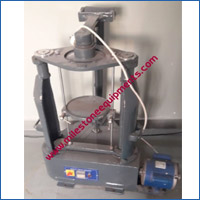
Sieve Shaker (Rotap Type)
RoTap Sieve Shaker machines have been engineered with reliable, rugged steel and alloy materials ready to withstand the everyday, harsh duty cycles. These units are fitted with heavy duty electric motor (1/4 HP) that enables the machine to provide efficient circular and hammering motions. Also available with Digital timer.
ME.GE – 1005002
Glass Beads
The Beads of the following size is available in One Kg pack
- Rounded Beads, made of glass, size 0.85 mm (passing 1 mm and retained at 0.85 mm)
- Rounded Beads, made of glass, size 0.425 mm (passing 0.85 mm and retained at 0.425 mm)
- Rounded Beads, made of glass, size 0.25 mm (passing 0.425 mm and retained at 0.25 mm)
- Rounded Beads, made of glass, size 0.18 mm (passing 0.25 mm and retained at 0.18 mm)
- Rounded Beads, made of glass, size 0.15 mm (passing 0.18 mm and retained at 0.15 mm)
- Rounded Beads, made of glass, size 0.075 mm (passing 0.15 mm and retained at 0.075 mm)
ME.GE – 1005003
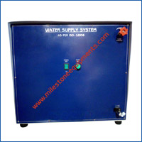
Water Supply System
Water supply system is designed to spray the water on the sample of COS test. it is provided with the flow control valve on the front and with two indicator one for power supply on and one for pump on.
 |
 |
|
In plane Permeability |
|
|
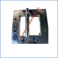
MI.GE-1006
In-Plane Permeability Test Apparatus
This test is necessary for drainage application. The permeameters can be of parallel flow or radial flow type. In either case, flow occurs along the plane of the permeamatre. In the apparatus, flow occurs radically outwards, from a central hole to the periphery of a circular specimen. The transmissivity is defined as the volumetric rate of flow per unit width of geotextile and unit hydraulic head.
Essential Accessories
- Overhead Tank
- Loading unit, 300 kPa capacity
- Range of Pressure: Upto 800 kPa
MI.GE-1007D
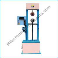
Universal Testing System for Geotextiles with Digital Load Indicator
The Universal Testing Machine is designed to carry out various tests on Geotextiles viz. Narrow & wide Tensile Strength, Trapezoidal Tearing Strength, CBR Push through and Puncture Strength etc. The machine gives a choice of seven constant rates of travel of the lead screw ranging from a maximum of 320mm/min to a minimum of 50 mm/min. The capacity of the machine is 100kN (10000kgf).It is provided with two no of load cell 100 KN and 10 KN
MI.GE-1007S
Universal Testing System for Geotextile with Microprocessor control
The unit is Digital Microprocessor control and speed regulating by servo controlled motor and the speed can be from 5 mm to 500 mm. This frame also be use with CBR test on soil, Marshall stability test on Bitumen and many more tests where speed required is with in the limit and maximum load is below 100 KN.
- Mounting …………….Floor Standing
- Capacity ……………..10000 Kg
- Load cell …………….10000 Kg Tension-Compression
- Force Measuring Accuracy………… Better than 1%
- Speed……………..…….. 50mm/min to 350
mm/min
- Position Measuring Resolution………0.1mm
- Computerisation……… Optional, RS 232 & Software
Note: - Additional software is also available viewing the test on excel
format.
The following attachments are available for Geotextile testing:
MI.GE-1007.1
Wide-Width Tensile Strength (Wide width strip Method)
Meets: - ASTM D 4595-86, ISO 10319:2008,
IS-13162 Part -5
Two clamping systems 8 cm wide and 22.5 cm wide are mechanical wedge type
and facilitate conducting Narrow Strip and Wide Width Tensile Strength tests
as per many international specifications. These grips allow simple and rapid
sample loading.
MI.GE-1007.2
Grab Tensile Strength Test (Breaking load and elongation of geotextile)
Meets: - ASTM D-4632,
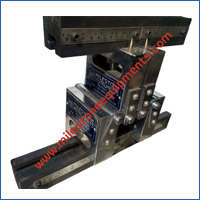
This test measures the ability of the geotextile to distribute concentrated loads. Specially devised clamps (25 mm wide) with a gauge length of 100 mm are placed across 200 mm square samples or 200 mm x100 mm samples. The sample is then subjected to tension at a specified rate until failure occurs. It is widely used by manufacturers as a quality control tool and as such is the most commonly reported tensile strength value. It can also be used for relative comparisons between geotextiles of the same type.
MI.GE-1007.3
Trapezoidal Tear Resistance Test
Meets: - ASTM D 4533, IS-14293
Geotextiles can be cut or punctured during field installation, which can create a possible condition by which strength is controlled by a tearing resistance. An outline of an isosceles trapezoid is marked on a rectangular specimen (150 mm x 75 mm) cut for the determination of tearing strength, (with a 6 to 9 mm cut) and the nonparallel sides of the trapezoid marked on the specimen are clamped in parallel jaws of the Tensile Testing System.
MI.GE-1007.4
CBR Push Through Test
Meets: - ASTM D- 6241, BS-6906 part 4, ISO-12236:2006
Fabric is clamped to give an inner diameter of 15 cm and a 50 mm CBR plunger is pushed centrally through a fabric at a specified rate. The load at failure is the push through load and when divided by the cross-sectional area of the plunger, gives CBR push through resistance.
ME.GE-1007.5
Puncture Test
Meets: - ASTM D-4833
The geotextile specimen is clamped to obtain an inside dia of 44.45 mm and force is applied through an 8 mm dia plunger till failure. The puncture strength so obtained is felt to reflect the fabric’s ability to withstand aggregate penetration.
MI.GE-1007.6 Puncture Test set Jaws (water proofing membranes)
Meets: - ASTM E 154
ME.GE-1007.7 Compression Strength Set
Sample size 50 mm diaMeets: - ASTM D 695
ME.GE-1007.8 Compression Strength Set
Compression Strength Sethead dia 6 inch
Flexural Strength set, Four roller Type ASTM C203
MI.GE-1008
Index Puncture Test (Ball Bursting Strength of Textiles)
The geotextile specimen is clamped to obtain an inside diameter of 44.45 mm and force is applied through steel ball having 25 mm diameter at the rate of 305 mm/min and continue at that speed until the specimen bursts. Record to the nearest 0.5 N the ball-bursting strength of the specimen.
Meets: - ASTM D-3787
 |
 |
|
Hydrodynamic Sieve Test Apparatus |
|
|
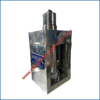
MI.GE-1009
Hydrodynamic Sieve Test Apparatus
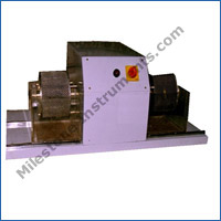
The apparatus consists of two test drums of 14 cm dia and 10 cm effective length with 16 nos. of 4 mm dia rods provided circumferentially at equal spacing to hold the geotextile specimen in position. Two troughs to contain the test drums are supported on horizontal axis, facilitating free rotation and capable of being filled with distilled water to a level of 20 mm below the drum axis. The clearance between the trough and the geotextile could be maintained at about 40 mm. The apparatus is provided with a motor drive and a change gear assembly to enable rotation of the drums at a speed of 20 rpm.
Note: - This machine is also available with servo controlled unit having 5-30 rpm speed with digital counter.
MI.GE-1010
Interface Friction Test Apparatus
This test method covers a procedure for determining the shear resistance of a geosynthetic against soil or a geosynthetic against another geosynthetic, under a constant rate of deformation.
Meets:- ASTM D 5321-02, EN ISO 12957-1:200
Note: Direct shear apparatus is to be order separately.
 |
 |
|
Abrasion resistance of Geo textile (Sliding Type) |
|
|
MI.GE-1011
Abrasion resistance of Geo textile (Sliding Type)
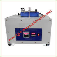
This test method covers the determination of resistance of geotextiles to abrasion using an abrasion tester. This test method at this point has only been evaluated for geotextiles— not geomembranes, grids, etc. Therefore, the test method is designated for geotextiles, not geosynthetics, as all products may not lend themselves to this test method for abrasion. If later developments indicate a wider scope for this test method, appropriate changes will be made. The assembly should be two parallel, smooth plates, one of which makes a reciprocating motion. The speed of the reciprocating plate should be adjustable between 10 and 115 double strokes per minute. The stroke length should be 25 mm (1 in.). The second plate is rigidly supported by a double-lever assembly to provide free movement in a direction perpendicular to the reciprocating plate. This plate is stationary during the test and must be well balanced so that a vertical load can be maintained by means of dead weights. Both plates are equipped with clamps at each end to hold the test sample and the abrading medium. The clamps have gripping surfaces adequate to prevent slippage of the specimen or the abrading material during the test.
Meets:-ASTM-D 4886-91, IS-14714, EN ISO 13427:199
 |
 |
|
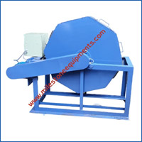
Abrasion resistance of Geo textile (Rotating Drum Type) |
|
|
MI.GE-1011
Abrasion resistance of Geo textile (Rotating Drum Type)
The test method simulates abrasion load on geo material. A mixture of stone chipping and water passes over geo material beg sample fixed in rotating drum
Details are as follows.
- Test Sample size 280×170 mm
- Drum Size 980 mm octagonal.
- With Digital revolution controller (At 5000±5 revolution
revering type) with revolution counter (Variation of 20 revolution at
40000 count)
- AC drive
- Branded Gear box with 1 HP 3 phase motor.
- Power transmission by Chain and pulley.
- Sample trolley type Tray.
- Voltage requirement 220 volts 50 HZ 1 phase
Meets :- IS-16653
MI.GE-1012
Creep tester
It consists of a loading frame for the specimen to be mounted, the load to be correctly applied, and strain monitored. The connections between jaws and loading apparatus have sufficient freedom that the load is applied uniformly across the width of the specimen. The jaws shall grip the specimen with sufficient firmness to allow minimum slippage.
Meets: - IS-14739
 |
 |
|
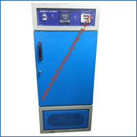
Environmental Chamber (Humidity Chamber) |
|
|
ME.GE-1013
Environmental Chamber (Humidity Chamber)
Double walled inside S.Steel and outside M. Steel painted with stove enamel door provided with glass window. Stainless steel water bath with heater is provided inside the chamber to create humidity in the chamber, provided with refrigeration to control temperature range from 5ºC to 60ºC +/- 2ºC and humidity is ambient to 90% Stainless steel water bath with heater is provided inside the chamber timer is provided to regulate the cyclic illumination. +/-5% and fitted with digital temp. & humidity indicator cum controller. Humidity is displayed in percentage.
 |
 |
|
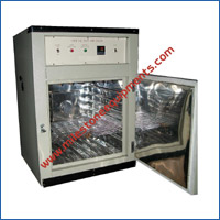
Laboratory Oven (Universal Memmert Type) |
|
|
ME.TH-1001
Laboratory Oven (Universal Memmert Type)
Double walled construction. Inner chamber made of anodized Aluminum / S. Steel Outer body made of mild steel is powder coated/painted. Temperature controlled by Digital Indicator and controller. The gap between the inner & outer chamber is filled with high grade glass wool to avoid the thermal losses and having perforated adjustable trays. Two pilot lamp on/off switch. Work on 220/230 VAC. Many Different size are available
 |
 |
|
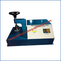
Bursting Strength Tester |
|
|
ME.GE-1014
Bursting Strength Tester
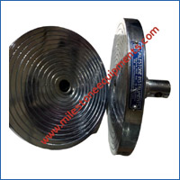
The Bursting Strength Tester is designed to find bursting strength of geotextile/fabric/leather/paper/paper board. A test specimen is held between two annular clamps under sufficient pressure to minimize slippage. The upper clamping surface which is in contact with the test specimens has a continuous spiral grooves. A circular diaphragm of rubber is clamped between the lower clamping plate & pressure cylinder so that before the diaphragm is stretched by pressure underneath it the center of its upper surface is below the plane of the clamping surface. The equipment is fitted with a motor driven cam mechanism, which increases fluid displacement on the lower side of the diaphragm at a specified rate. The equipment is fitted with an arrangement, which automatically brings down the pressure and stops the motor on completion of the test cycle. A maximum reading type pressure gauge gives the bursting pressure. The equipment is raggedly designed to give a long & trouble free life.
TECHNICAL SPECIFICATION
- Capacity: 35kg /cm² and above
- Opening in upper clamp: 30.5 mm diameter
- Opening in lower clamp: 38.1 mm diameter
- Rate of fluid displacement: 95 cc/ minute
- Test fluid: Glycerin
- Gear Box: Worm reduction type
Note: Digital type pressure gauge with and without pneumatic clamp type also available.
 |
 |
|
GSM Cutter |
|
|
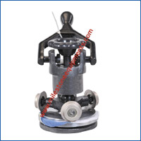
ME.GE-1015
GSM Cutter
GSM Round Cutter offered come fitted with precision finished and superior grade high strength blades as well as other associated metal parts that ensures uniform cutting of geotextile and other material. We have two type of GSM cutter details are as follows.
Technical Data:
- Body of the Machine - Cast Iron
- Cutting Tool - Bottom Pad & Blade
- Diameter Size: 112.8 mm
- Pad & Blade life up to 6,00,000 Cuttings
- Machine Weight - 10.5 Kgs Approx
Technical Data:
- Body of the Machine - Cast Iron
- Cutting Tool - Bottom Pad & Blade
- Diameter Size: 140 mm
- Pad & Blade life up to 6,00,000 Cuttings
- Machine Weight - 14.5 Kgs Approx
Note: Digital type pressure gauge with and without pneumatic clamp type also available.
 |
 |
|
Colour Matching Cabinet |
|
|
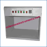
ME.GE-1016
Colour Matching Cabinet
Colour Matching Cabinet with D65. TL84.Illuminant A.UV-Light. CWF (Cool White Fluorescence.) D50.Simulated Sunlight. CDL (Cool Day Light.)
Dimension:
- Outer dimension : 720mm x 520mm x 650mm
- Viewing area : 595mm x 460mm x 410mm
 |
 |
|
Air Permeability Tester |
|
|
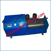
ME.GE-1018
Air Permeability Tester
Air Permeability tester up to with four different type adaptor 5 cm2, 10 cm2, 20 cm2 & 38 cm2, with Manometer & Rota Meter.
 |
 |
|
DIN Abrasion Tester |
|
|
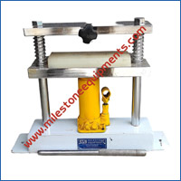
ME.GE-1019
DIN Abrasion Tester
 |
 |
|
Die Press |
|
|
ME.GE-1020
Die Press
 |
 |
|
Dumbbell Die Cutter |
|
|
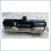
ME.GE-1021
Dumbbell Die Cutter
Used to Draw Sample for testing from the sheet.
Made of high Quality Die steel with accuracy.
Available in many size.


